faqs
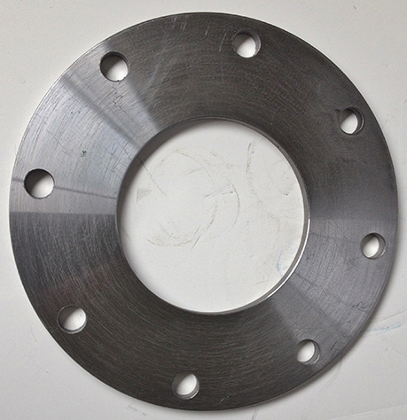
Place the flange on a flat surface. Lay a straight edge ruler across the face of the flange. Place the leading edge of the ruler, dissecting the middle of two bolt holes that are on opposite sides of the flange and the furthest apart from each other. The straight edge should appear to dissect the flange in equal halves.
The bolt hole diameter is the distance from the center of the left side bolt hole to the center of the right side bolt hole.
Take the flange and lay on a flat surface. Place a straight edge ruler across the face of the flange. Place the ruler’s leading edge dissecting the middle of two bolt holes that are on opposite sides of the flange and the furthest away from each other. The straight edge should appear to dissect the flange in equal halves.
The inside diameter is the distance from the inside edge of the left side of the interior opening to the opposite edge of the right side’s interior edge.
Lay the flange down on a flat surface. Place a straight edge ruler across the face of the flange. Place the ruler’s leading edge dissecting the middle of two bolt holes that are on opposite sides of the flange and the furthest away from each other. The straight edge should appear to dissect the flange in equal halves.
The outside diameter is the distance from the flange’s outside edge of the left side measured to the opposite right side’s outermost edge.
If using a ruler: lay the flange down on a flat surface. Place a straight edge ruler across the face of the flange. Place the ruler’s leading edge dissecting the middle of two bolt holes that are on opposite sides of the flange and the furthest away from each other. The straight edge should appear to dissect the flange in equal halves. Keeping the ruler in place, take the measurement of either the left side or right side bolt hole’s opening.
If using a caliper: lay the flange on a flat surface. Zero the caliper, then choose any bolt hole on the flange to measure. Place caliper’s spacers inside and open it fully. While watching the caliper’s reading (if digital) rotate the caliper around the bolt hole while applying outward pressure on the caliper’s spacers. The highest reading the caliper displays is the bolt hole’s diameter.
The only difference between a Pipe (IPS) and Tube flange is the inside diameters (ID). A tube flange’s ID will be only slightly larger than the nominal size while an IPS flange’s ID will be .57 to .88 inches larger than nominal. For example, an 8 inch tube flange’s inside diameter is 8.06 inches, while the equivalent 8 inch pipe (IPS) flange’s ID is 8.72 inches.
All other dimensions such as bolt hole diameter, bolt hole size, and outside diameter are the same. Pipe Fitting Direct’s flange part numbers are designed with a “T” after the flange’s nominal size to denote a tube size and a “P” to designate a Pipe or IPS size.
A flange’s nominal size is not the actual inside diameter (ID) of a flange. Nominal size of the flange is determined by the actual tube or pipe size that the flange is welded against. For example, if a flange’s ID measures 5.66 inches, its nominal size is not rounded up to 6 inches. The flange’s nominal size is 5 inches as it will fit the outside diameter of a 5 inch NPS (National Pipe Standard) pipe.
When a flange’s thickness is less than the standards of thickness determined by ANSI class 150, it is considered a light weight flange. All other dimensions meet class 150 requirements. Light weight flanges are typically used where the flange does not require load bearing.
Pressure ratings for flanges are designed to ANSI standards of 150 lb, 300 lb, 400 lb, 600 lb, 900 lb, 1500 lb, and 2500 lb. The most common terminology used is the pound reference, although the more formal reference is by class, such as Class 150 flange.
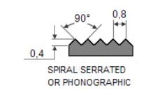
The machined gasket surface area of the flange. This rough surface helps the flange's gasket stay in place and provide better leak prevention.
Bore (also known as the nominal wall thickness of matching pipe)--the measure of the flange wall thickness, which matches the inside dimension of the pipe being used. The lighter the pipe is, the larger the bore; conversely, the heavier the pipe, the smaller the bore.
The reducing flange is similar in every respect to the full size of the flange from which the reduction is to be made. Typically used to save costs in a system by transitioning to a smaller size pipe, reduction flanges are availabe to step down 1 or 2 nominal sizes.
The reducing flange is described in the same manner as a reducer--that is, the large end first, the reduction second. For example PFDLW8x6P has all the dimensions of an 8 inch pipe flange (PFDLW8P) except it has the ID/bore diameter of the 6 inch pipe flange (PFDLW6P)
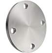
A blind flange, which has no bore, is used to close ends of piping systems. A blind flange also permits easy access to a line once it has been sealed. It has all the mounting dimensions of an ANSI flange.
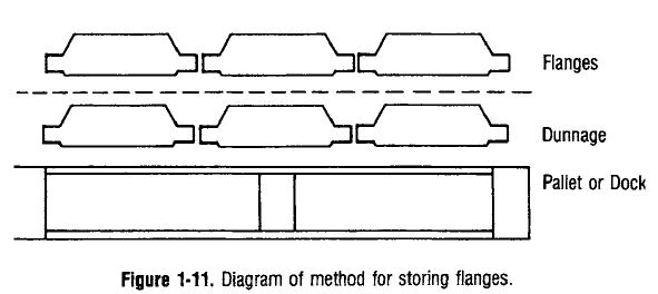
The preferred storage method for flanges is face down on wooden pallets or wooden docks, using dunnage to separate each layer of flanges, as shown in Figure 1-11. (For dunnage, use wooden strips, paneling, cardboard,plywood, etc.) Special care should be extended to the flange facing during storage or shipment.
Used to designate a pipe's OD, ID and thickness. As schedules increase in its number, so typically does its pressure rating. Many schedules are identical in certain sizes.
Typical schedules are:
- Schedule 10
- Schedule 20
- Schedule 30
- Schedule 40
- Schedule 60
- Schedule 80
- Schedule 100
- Schedule 120
- Schedule 140
- Schedule 160
Just as it describes, seamless pipe does not have a lateral weld to join the pipe's two sides together to make a circle. This type of pipe is made by heating billets and advancing them over a piercer point. The pipe then passes through a series of rolls where it is formed to a true round and sized to exact requirements.
The difference between API and ANSI flanges is the material from which they are fabricated and the higher working pressure at which API flanges may be operated. API flanges are manufactured primarily for use with oil industry high-strength tubular goods. The API 6A and ANSI B. 16.5 flanges are similar dimensionally but they cannot be interconnected without affecting the overall working pressure rating.
TBE stands for Threaded-Both-Ends. Therefore, both sides of the pipe nipple are threaded.
Merchant is an industry designation for a lesser grade of steel. Sometimes referred to as "black". All dimensions are same as a half coupling.
- API - American Petroleum Institute
- ASA - American Standards Association
- Asb - Asbestos
- ANSI - American National Standards Institute, Inc.
- ASME - The American Society of Mechanical Engineers
- ASTM - The American Society for Testing and Materials
- AWWA - American Water Works Association
- BE - Beveled End
- BW - Buttweld
- BBE - Bevel both ends
- Bbl - Barrel
- Bdr - Bleed ring
- Bfy - Butterfly (valve)
- Bld - Blind (flange)
- BLE - Bevel Large End
- Blk - Black (pipe)
- BOE - Bevel one end
- BOM - Bill of materials
- BOP - Bottom of pipe
- CI - Cast iron
- CS - Cast Steel, Carbon Steel, Cap Screw
- F&D - Faced and drilled (flange)
- FE - Flanged ends/flow element
- FF - Flat/Full face
- F/F - Face of flange
- FS - Forged Steel
- FW - Field weld/Firewater
- Flg. - Flange
- FSD - Flat side down
- FSU - Flat side up
- Flgd - Flanged
- ID - Inside diameter or bore
- IPS - Iron pipe size
- MSS - Manufacturers Standards Society of the Valve and Fittings Industry
- NPS - Nominal Pipe Size
- OD - Outside diameter
- PE - Plain Ends
- PS - Pipe support
- PBE - Plain both ends
- Pdl - Paddle (a blind plate between flanges)
- PLE - Plain Large End
- POE - Plain one end
- PSE - Plain small end
- RF - Raised face
- SO - Slip -on (flange)
- Sch - Schedule (of pipe or fittings)
- Sdl - Saddle (pipe)
- Std - Standard (a pipe or fitting schedule)
- Skt Bld - Skillet blind (plate between flanges)
- Scrd - Screwed (ends)
- Spec bld - Spectacle blind (plate between flanges)
- T&C - Threaded and coupled
- T&G - Tongue and groove (flange facing)
- Tbg - Tubing
- Thk - Thick
- TLE - Thread large end
- TOE - Threaded one end
- TSE - Thread small end
- Typ - Typical (repeat the same item)
- Thr'd - Threaded
- Un - Union
- Va - Valve
- Vac - Vacuum
- WE - Weld end
- WI - Wrought Iron
- WN - Weldneck (flange)
- WP - Working Pressure
- WT - Wall Thickness/weight
Some excerpts for this section are from "Pocket Guide to Flanges, Fittings, and Piping Data" by R.R Lee